
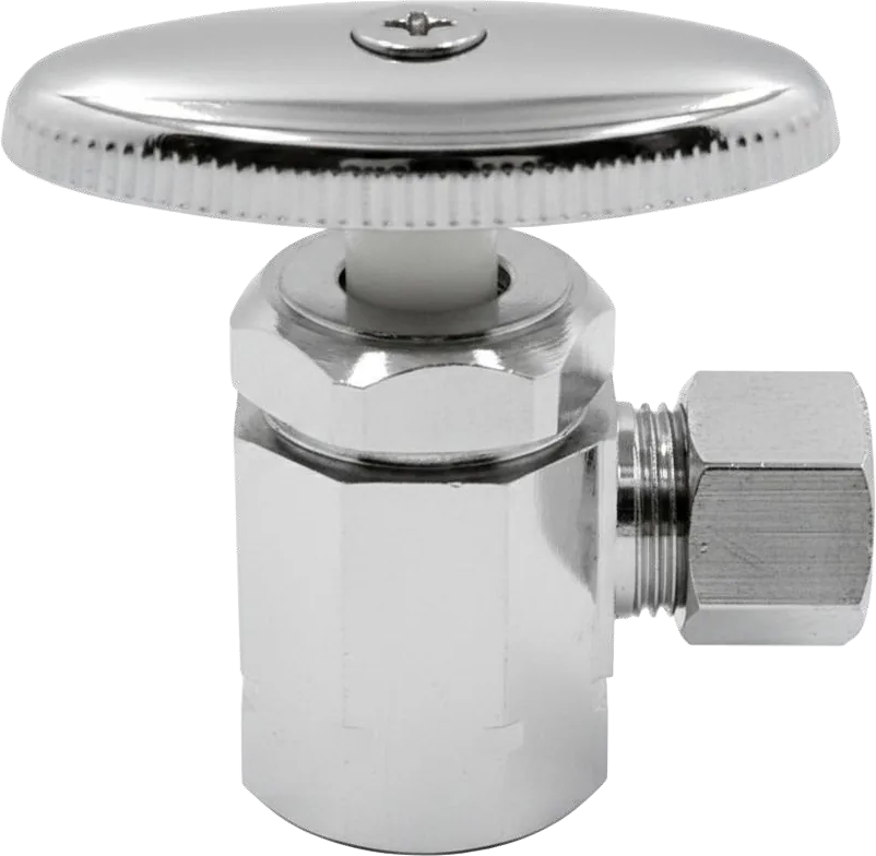
Angle Stop Valves
MODEL:
- LA 1
- LA 2
- LA 3
- LA 4
- LA 5
- LA 18
- LA 26
Warning & Notes
Turn off the water supply and release system pressure before installation.
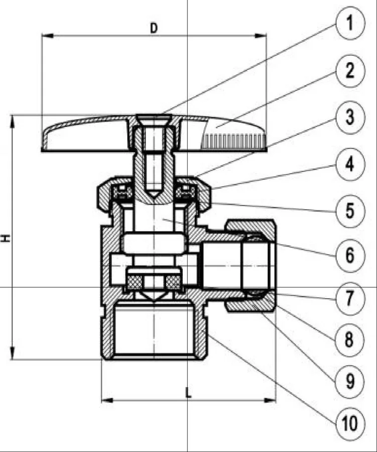
Dimension (mm)
| Model | H | L | L1 | D |
|---|---|---|---|---|
| LA 1 | 49.5 | 39.75 | 24 | 51 |
| LA 2 | 49.5 | 36.75 | 20.5 | 51.2 |
| LA 3 | 50.5 | 38.1 | 20.5 | 51.2 |
| LA 4 | 50.5 | 42.2 | 24 | 51.2 |
| LA 5 | 50.5 | 42.2 | 24 | 51.2 |
| LA 18 | 52 | 43.4 | 24 | 51.2 |
| LA 26 | 50 | 39.9 | 24 | 51.2 |
Installation
- Apply PTFE (Teflon) thread seal tape to the external male threads of the supply pipe stub clockwise around the male pipe threads 5 to 6 times
- Thread the valve onto the pipe by hand. Use a wrench on the flats of the brass body and tighten securely
- Rotate the valve until the outlet connection points right. Do not over- tighten
- Assembling the Outle compression ring and
Maintenance
Leakage Around the Stem (Below Handle):
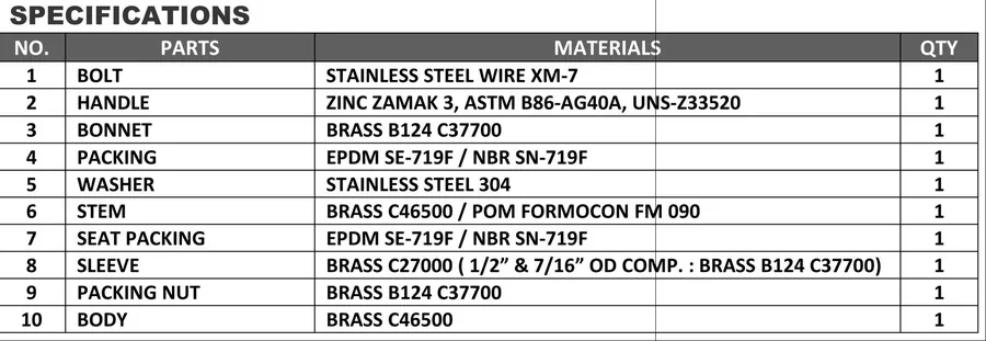
Slightly tighten the packing nut (approximately 1/8 turn) with a wrench. Do not over-tighten.
Valve Fails to Shut Off Completely (Persistent Dripping):
Isolate the water supply, remove the bonnet assembly, and inspect the seat washer. Clean or replace the washer as necessary.
Tools Required
- Adjustable Wrench or Pipe Wrench
- PTFE (Teflon) thread seal tape