
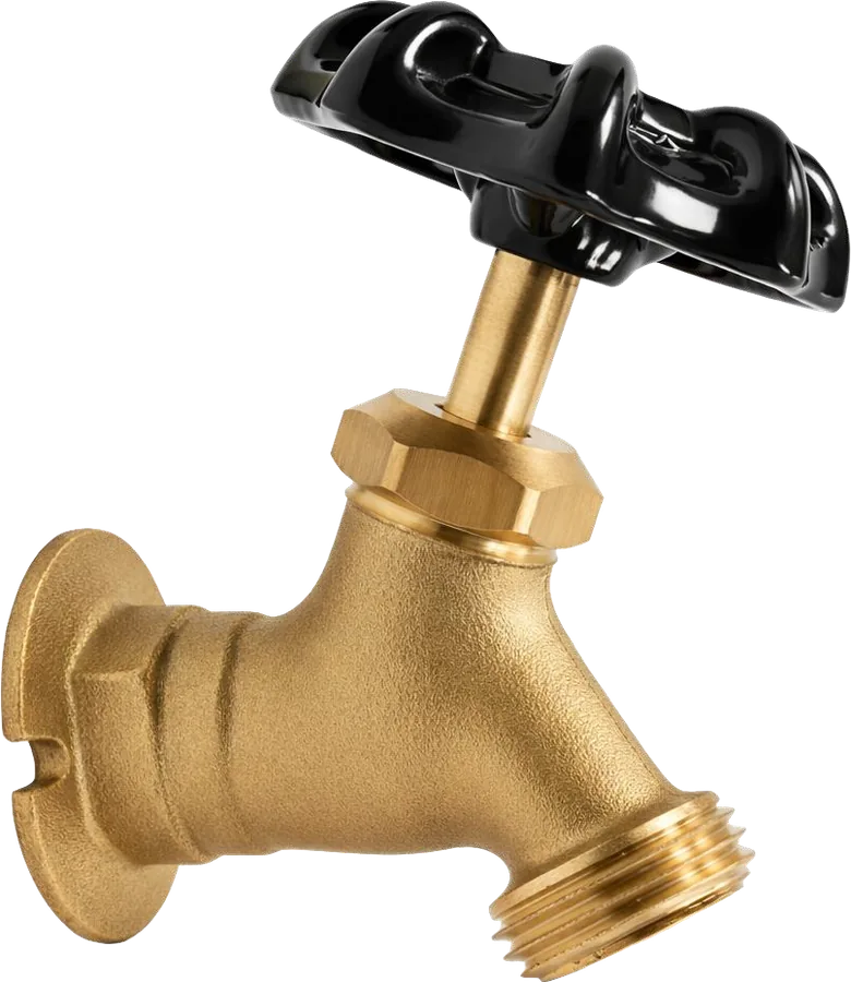
Sillcock Valves
MODEL:
- LB 29 (3/4" MHT)
- LB 28 (1/2" MHT)
Warning & Notes
Turn off the water supply and release system pressure and allow Hot water to cooling before installation.
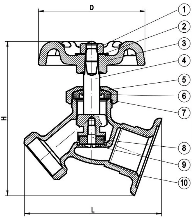
Dimension (mm)
| Model | H | L | D |
|---|---|---|---|
| LB 29 | 78 | 69 | 53.5 |
| LB 28 | 81.5 | 69.7 | 53.5 |
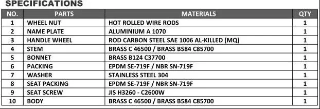
Installation
- Apply PTFE (Teflon) thread seal tape to the external male threads of the supply pipe stub clockwise around the male pipe threads 5 to 6 times
- Thread the valve onto the pipe by hand. Use a wrench on the flats of the brass body and tighten securely
- Rotate the valve until the hose connection points right. Do not over- tighten.
- Close the hand whee on the water supply a connections for leaks
Maintenance
Leakage Around the Stem (Below Hand-wheel):
Slightly tighten the packing nut (approximately 1/8 turn) with a wrench. Do not over-tighten.
Valve Fails to Shut Off Completely (Persistent Dripping):
Isolate the water supply, remove the bonnet assembly, and inspect the seat washer. Clean or replace the washer as necessary
Tools Required
- Ad PTFEjustable Wrench or Pipe Wrench
- (Teflon) thread seal tap